![]()
 Home
Home Products
 Cameras
Launch Monitors
Cameras
Launch Monitors Software
 Enclosures
 ProTee
 E6 Courses
 Business
 Tech News
 View Cart

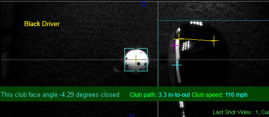
Club Data Detection
Note that all below instructions assume that you are using CP version 10.0.3.3 or higher
![]()
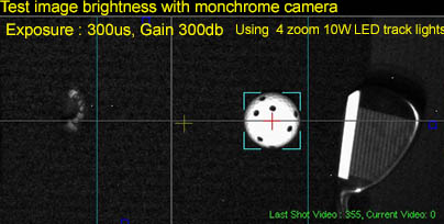
The below images are all from shot video frames sent in by customers.
Thus they may appear a tad out of focus and blurry.
i.e. they have not been doctored or enhanced
![]()
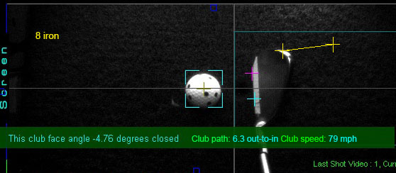
Method of club detection
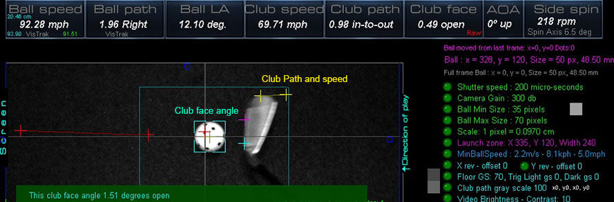
The basic method is to scan back from the stationary ball on the mat (i.e. before ball strike)
looking for pixels that are above the set floor gray scale level (GS).
So we're looking for a transition from the floor GS to a GS that is higher
i.e. a positive edge transition
Two main scans are made from the first frame behind the ball.
1 above the ball to the center of the ball
Shown in Pink/Red
and 1 below the ball to the center of the ball.
Shown in Aqua
Once found, this will give us the club face angle of the ball 1 frame behind the ball strike frame
A second set of two scans are then made from 2 frames behind the ball
Again, two main scans are made from the first frame behind the ball.
1 above the ball to the center of the ball
and 1 below the ball to the center of the ball.
Once found, this will give us the club face angle of the ball 2 frames behind the ball strike frame
In addition, the top most transition edge is noted in order to measure ball path and speed
Shown in Yellow
![]()
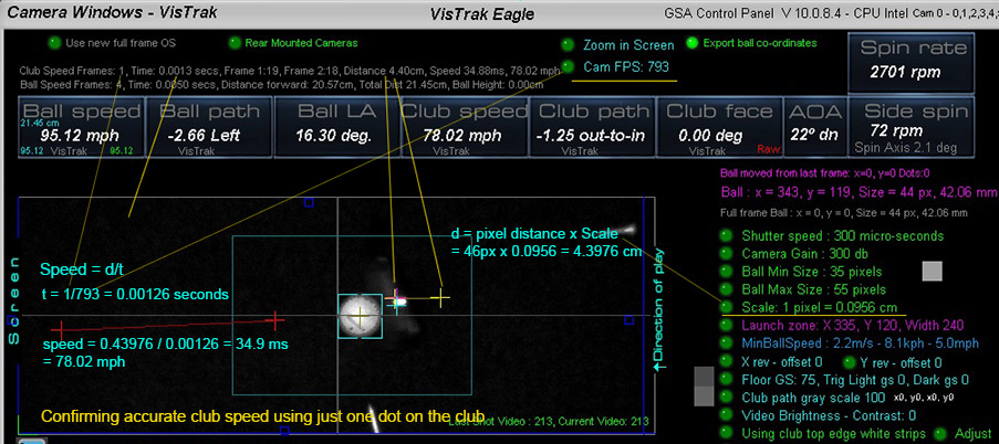
Club Sped detection
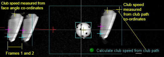
You can opt to select either club path or club face co-ordinates to measure club speed
![]()
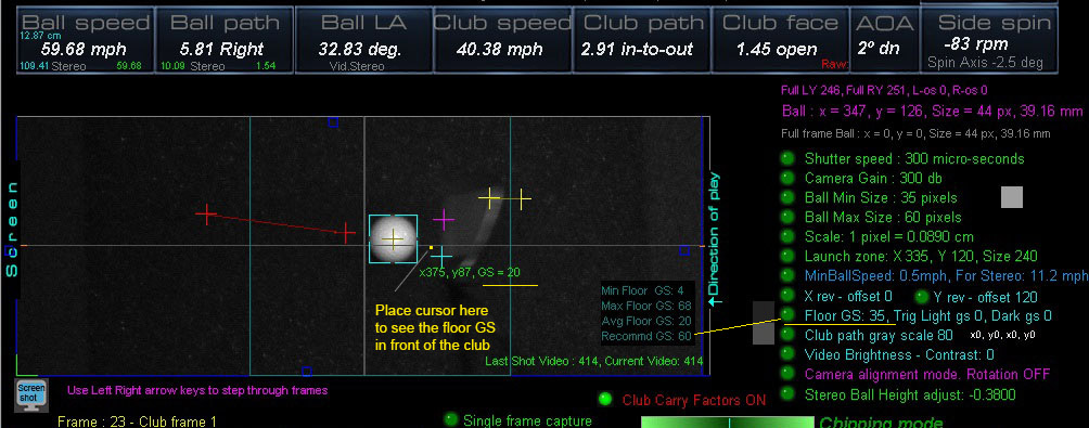
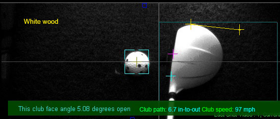
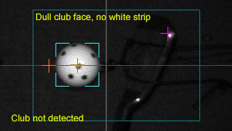
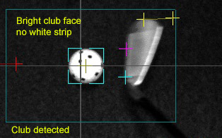
Detecting club data with or without reflective stickers
In either case, the method is exactly the same as described above.
i.e. we are looking for edge transitions from the floor GS to above floor GS.
As such, it's just a matter of fine tuning the floor GS to match the transition edge
In the above example, a white sticker was applied to the leading edge of the driver.
This vastly increases the transition threshold level from the floor GS of 60 to the sticker GS of 150.
Note that the recommended Floor GS setting is now shown in the camera panel
To initialize this setting, click the soft trigger button without a ball on the mat.
The system will then measure the average Floor GS of all the pixels within the Launch Zone area
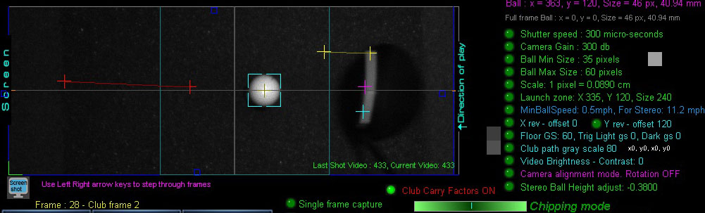
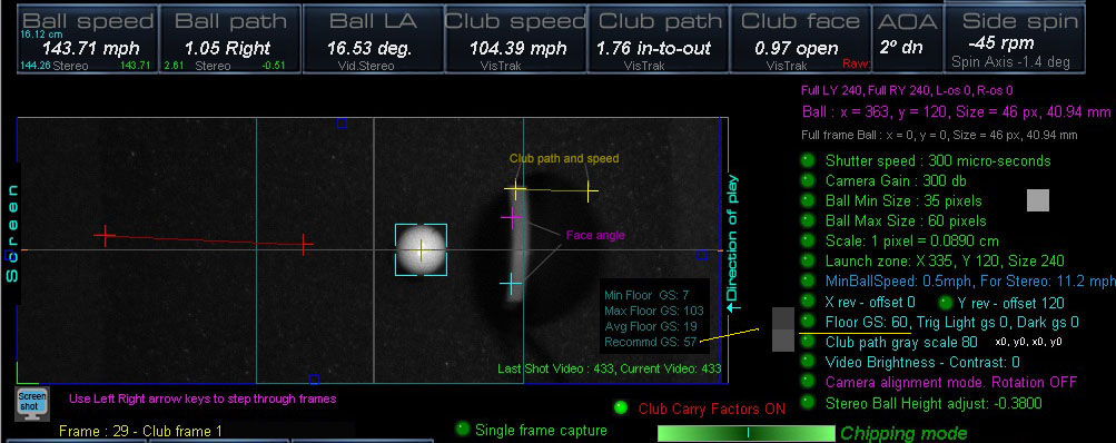
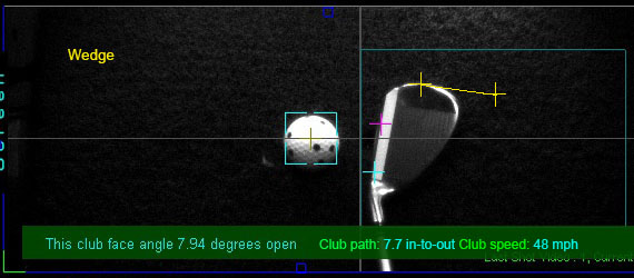
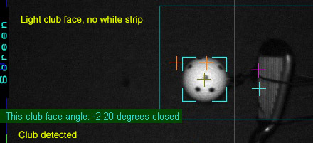
This is club frame 2 from the previous shot
In the above example, a white sticker was not applied to the leading edge of the club.
Thus the transition threshold level from the floor GS to the leading edge of the club is significantly lower
than it would be if the club featured a white sticker.
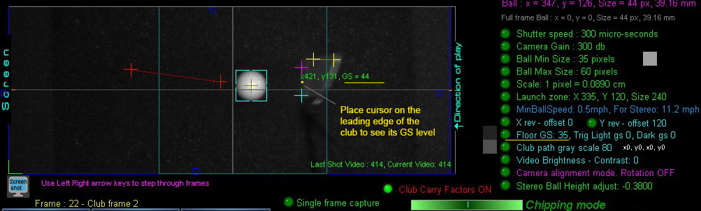
In order to detect the leading edge of the club without a white sticker,
we need to find out what the GS level of the club leading edge is.
In this case it is 44.
(using the shot video in the camera panel)
And what the Floor GS level is (see previous image)
In this case it is 20.
We then just need to set the Floor GS to a level in between these 2 levels
In this case level 35 works well.
Click the "Re-calculate" button to see the results of the club detection.
Thereafter, all club data should be accurately detected for all other shots no matter how bright the club is.
Of course, there is a limit to this.
If you are using a dark or black club or your lighting is such that there's essentially no Floor GS to Club edge GS level transition or deviation,
then there's no way to detect the club.
i.e. if you can't see the club at all because it blends into - or is darker than - the underlying surface,
then the cameras won't see it either.
Sometimes the leading edge can appear faint
Increasing the Video Contrast helps
Of course, if you using white clubs or clubs with a white strip already on them, then there shouldn't be any problem in detecting the club.
![]()
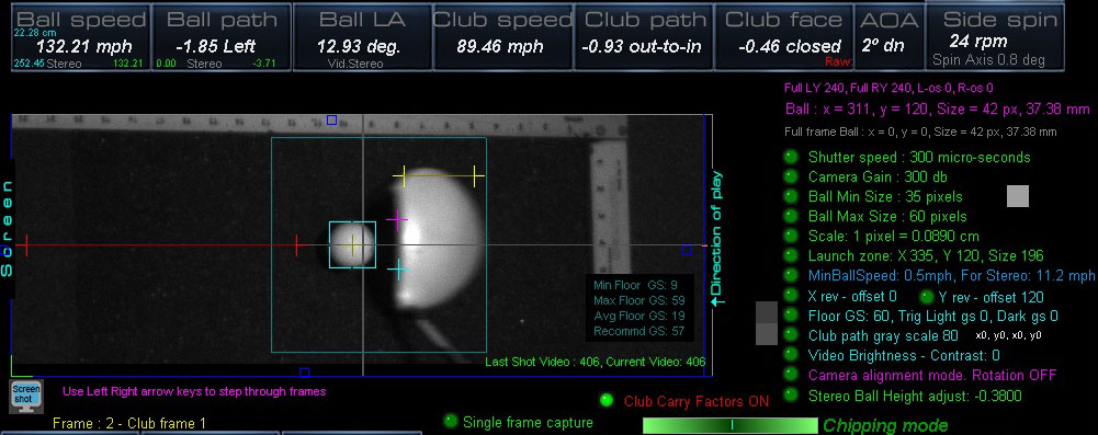
Club markings
Generally speaking, our systems (like $7,000 plus Uneekor and Foresight systems) require bright markings on the club
in order to accurately detect club data.
However, in contrast to other systems that require 2 to 4 tracking dots to be applied to every club,
our systems only require one bright white strip to be adhered to the club.
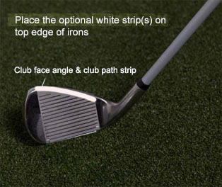
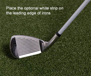
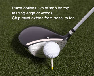
One or two white strips can be applied to the leading edge or top edge of irons and the top edge of woods
in order for the system to detect more precise club face angle, speed and path.
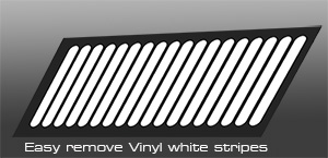
You can use supplied sticky-back white glossy photo paper as club strips
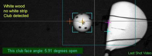
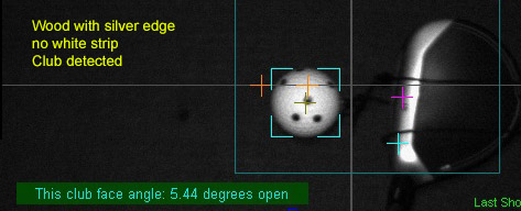
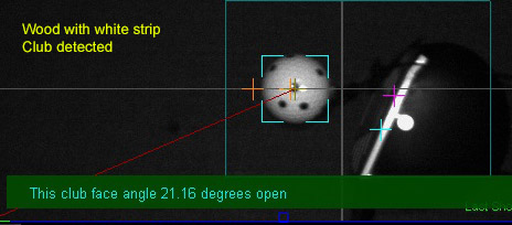
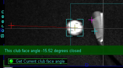
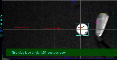
The below examples are from the VisTrak LX2 using the new top view IR LED lighting
Note: You can now click a button to get the current club face angle in the current frame.
LX2 examples
SCX, Eagle, EVi examples
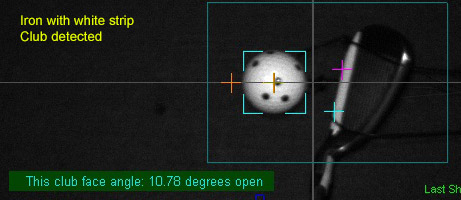
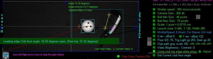
Top Edge white strip mounting for irons
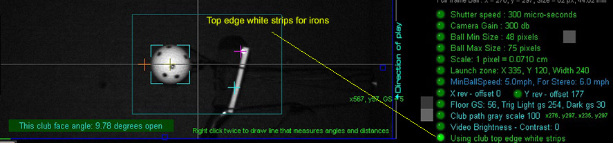
If hitting irons on the down swing or you have mounted the cameras behind the player, the club face will be out of view.
This problem is solved by placing the club marking on the top edge of the club (like the Uneekor systems do).
However, the measured face angle from the top strip has to be adjusted to get back to the leading club face angle.
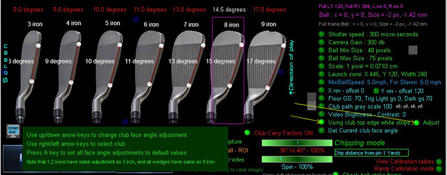
The above image shows the default adjustments required for each iron club.
You can change the amount of top face edge angle to leading edge angle adjustment for each club.
![]()
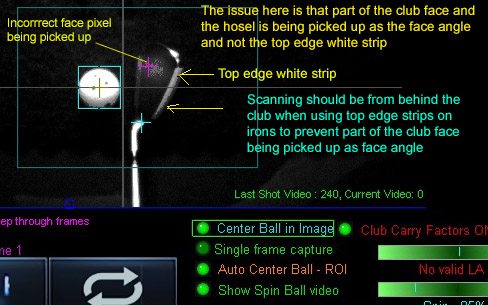
New : Club face issue when using top edge strips with irons now resolved
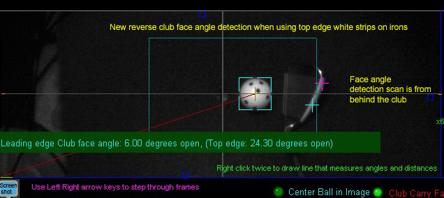
Club face angle detection scan is now done from behind the ball with irons when using top edge white strips
to prevent the issue shown in the below image from occurring
![]()
Lighting
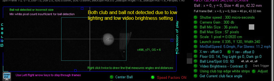
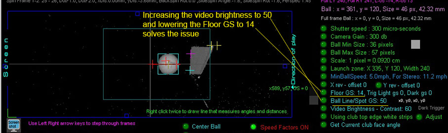
These images were taken here at GSA Golf using optimal lighting.
Adjusting the lighting can make a significant difference and vastly improve the club detection
![]()
New: You can now click a button to get the current club face angle in the current frame.
![]()
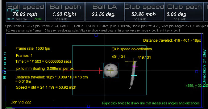
New: Club speed varification
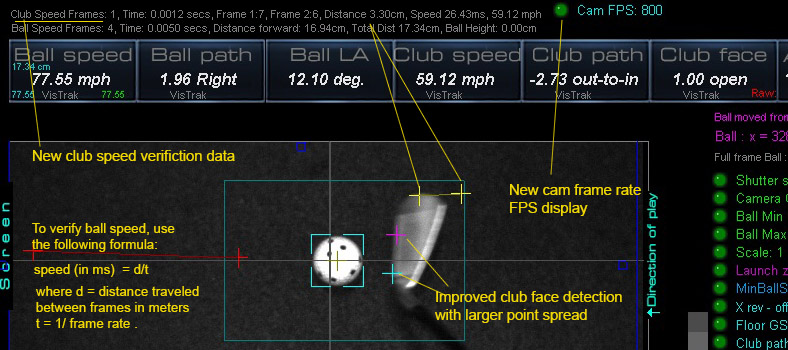
Verifying accurate club speed example
Verifying accurate club speed example 2
The importance of Club Face angle and Path Cross Hairs
In contrast to other camera club tracking systems,
GSA Golf's VisTrak systems show the cross hairs of the detected club face angle and path.
Without these cross hairs, there's no way a user can verify that the systems are actually detecting the club data.
i.e. they are just showing a shot playback video of the club
and that is no indication that the club data is actually being detected and reported by the system.
![]()
ProTee VX
$6,499
![]()
ProTee did have a YouTube club tracking video showing club detection cross hairs
but I haven't seen these in any of the real playback videos
Currently, I have no idea how ProTee's VX system is using AI to capture club data but apparently they do.
I haven't recently looked to see if the above green club cross hairs are actually shown on all the post shot video feed playbacks
but if they are, then that's amazing!
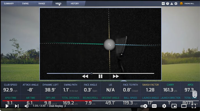
Currently I'm only seeing ProTee VX club playback videos like the above without cross hairs
BTW I'm not saying that the club detection accuracy without cross hairs is incorrect,
just that the user cannot see and verify that the systems did actually detect the club data correctly.
![]()
Uneekor
$7,000
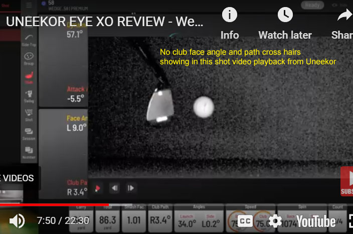
Likewise, Uneekor - at least in all the post shot playback videos I've seen -
don't appear to be showing any club detection cross hairs either.
![]()
TruGolf Apogee
$ 9,000
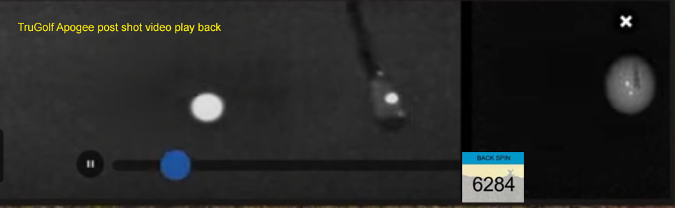
Based on the above Apogee low resolution post shot video playback image,
I have no idea how the Apogee captures all the club data (face angle, path and speed) using just one dot
plus all ball spin parameters (i.e. back and side spin)
![]()
GSA Golf VisTrak SCX
$1,699
In contrast, the VisTrak systems always show these cross hairs
so the user can see we have detected the correct club face angle and path
![]()


![]()