![]()
![]()
ProX 3D Model Course Designing with 3dStudio Max
Tutorial 2
![]()
Step 6.
Creating textured area objects. Greens,bunkers,fairways are textured area objects. The following method applies to all area textured objects that have a fringe.
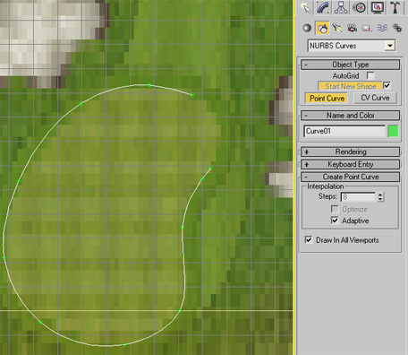
First we draw an outline of the object.
Step 1. All drawing will be done in the Top viewport window so select this and zoom into the desired object in the background image. Hide the overlaying Rough object ( select the Rough object, right click in viewport and Hide Selected).
Step 2. Select the Shapes Tab in the top right hand menu.
Step 3. Open the combo box and select NURBS curves and then Point Curve. (A Line spline also works but doesn't make quite such a nice curve).
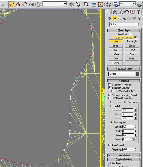
Step 4. In the Rendering rollout, set the Enable in Viewport, set the Rectangular radio button on and set the Length and Width both to zero.
Step 5. Move the mouse cursor to any outside perimeter point on the object and in an anti-clockwise direction click points around the objects perimeters. As you do this you will see a nice curved line following the cursor. Where the perimeter is a slow curve you can click a point at the next curve increase. More points will be required on tight curves.
Step 6. When you have completed the curve and reached the starting point of the curve again a message box will appear asking you to Close Curve? Select Yes.
Note: If the object should have a fringe then this should be the outside perimeter of the fringe.
Step 7. Name the object "Cutout..." where ... should be replaced with an appropriate name of the object. ie "Green", "SandBunker" etc..
All cutout objects must have their name start with the string "Cutout" eg "CutoutGreen", "CutoutSandBunker1" etc...
Surrounding surface cutout.

The above shot shows two bunkers, the green and a footpath all covered with the rough surface object.
Our objective now is to remove all polygons of the Rough object that lie within the borders of the objects (Green and the two bunkers in this case). Effectively we want to cut out holes in the Rough object that have the same form and size as the underlying object.
As we created our surface objects we created a Cutout object for each of them. This will now be used to cut a hole in the Rough object to the exact same form as the object itself.
Step 1.
Before we start we should increase the polygon resolution of the surrounding Rough that lies near the objects. To do this select the Face button in the Selection rollout and select an area around the cutout objects. (as shown above).
.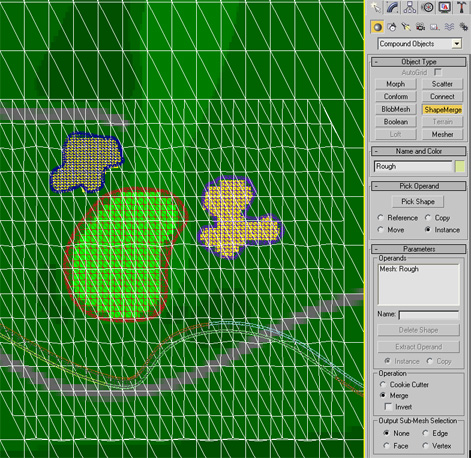
Then press the Subdivide button to double the resolution for this area.
Step 2. Now, with the Rough object selected, select Compound Objects from the geometry combo box rollout. The screen should now look like the above. You should see the "Mesh: Rough" in the Operands list box.
Step 3. Press the "Pick Shape" button and then the H key on your keyboard. From select listing - which will now only show suitable shape objects - select the Cutout object (in this case the GreenCutout object).
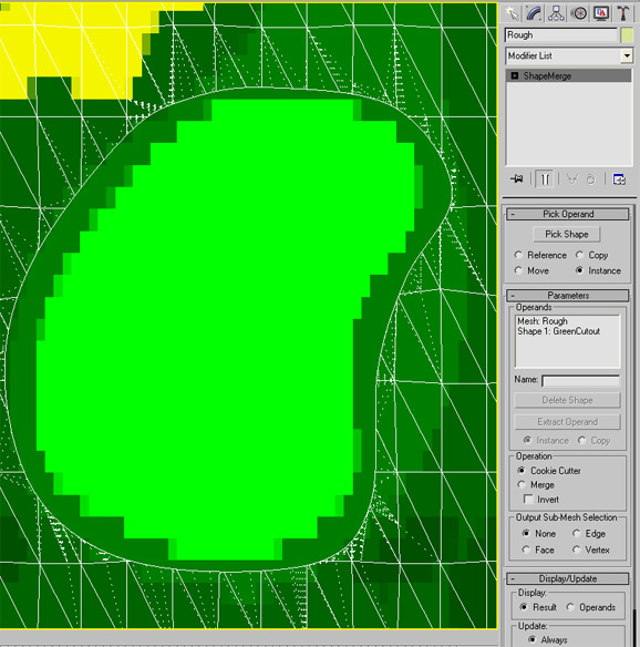
Step 4. Select the Cookie Cutter from the Operation box. You should now immediately see that a hole has been made in the rough object with the exact shape as the Cutout object and that the rough polygon face edges have been made to surround the hole.
Our Green now has it's own rendering space and can be rendered without interference from the rough.
Creating the Fringe
Having made our cutout in the rough, we have generated more polygons around the object ( in this case the Green). In order to make the fringe line up properly with the surrounding rough we have to create the fringe with the same number of edge vertexes. This requires a little manual line drawing work.
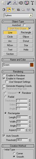
Step 1. Select Shapes from the Create menu and then Splines from the combo box. Select Line as the Object Type.
Step 2. Set the Snaps Toggle button on (magnet 3 button in top menu bar) and click around all the inside vertexes of the Rough object cutout. As you move around a blue cursor will appear when the next vertex is near. Click every time the blue cursor appears. Use the mouse wheel to zoom-in-out and the mouse middle button to pan (move) the view when necessary. Select Close Spline when finished and name the line appropriately. (in this case "GreenFringe".
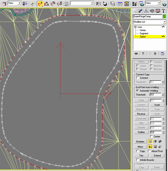
Step 3. Select the Modify tab and select the Spline option in the Line tree list.
Step 3. Set the Outline value in the geometry rollout to a suitable value (2, 3, or 4). An inner outline will appear ( if the outline appears on the outside then set the value to a minus/negative value).
Step 4. Delete the original Line ( now shown in Red).
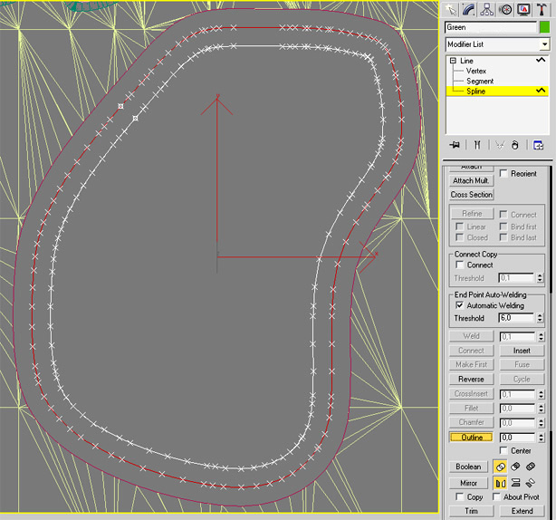
Step 5. We now make a copy of the line for the main body of the object (in this case the Green).
With the spline object still selected, press the ctrl/V key (or right click on the object and select Clone). Select the Copy option in the Clone window ( not Instance) and name the clone appropriately.(in this case"Green").
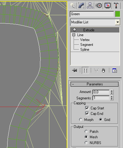
Step 6. Select the fringe again and select Rectangular rendering and the Enable in Viewport otion on. Set the Width in the Rendering rollout to double that of the outline value made previously. eg if the outline value was set to 2, then set the Width in the Rendering rollout to 4.
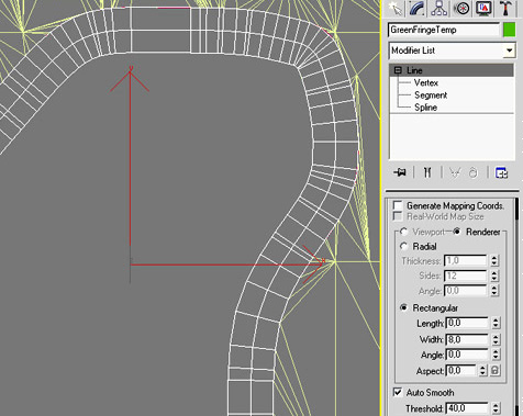
Your fringe should now look similar to this.
( Do not convert fringes to Editable Meshes or Patches.)
Creating the Body
Step 1. Select the spline copy made earlier. (in this case the Green spline object)
Step 3. Select the Modify tab and select the Spline option in the Line tree list.
Step 3. Set the Outline value in the geometry rollout to a suitable value (2, 3, or 4). Another inner outline will appear ( if the outline appears on the outside then set the value to a minus/negative value).

Step 4. Delete the original Line ( now shown in Red).
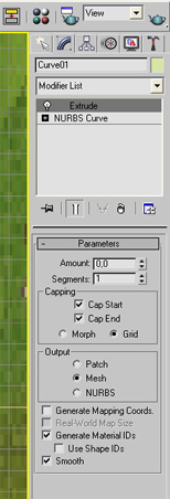
Step 5. Open up the Modifier List and select Extrude form the Modifier list.
Step 4. In the Parameters rollout of the Extrude modifier set Amount to 0, Capping to Grid and Output to Mesh.
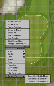
Step 5. Right click on the object and select Convert To: Convert to Editable Patch

Your object (Green in this case) should now look something like this.
If the grid doesn't show then open up the Object Properties window (right click on the object to access the properties window). When open, switch the Edges Only option off in the Display Properties.
All surface objects can be made like this including the fairways, tee boxes and sand bunkers. Repeat these steps for all other surfaces on your course hole.
Remove non required backface polygons
Using this method we can create any surface shaped object . The only problem is, although the objects are flat, they still have two sides. Top and under sides. If we leave the object as it is we will be wasting valuable rendering time rendering the under side of the object that will never be seen.

In order to remove the underside polygons - which are known as Backfaces - select a Bottom viewport (right click in the top right hand corner of the viewport and select Bottom)
Select the object and then the Editable Patch from the Modifier list. Select the Patch (or Face if its an Editable mesh ) button and click the Ignore Backfacing option on.
Select all the faces in the object - they will show up red - and then just press the delete key. Doing this halves the number of faces in the object.
Do this for all surface objects you create except fringes.
That's it as far as drawing the main surface objects is concerned.
We are now ready to apply nice textures to our surface objects.
Go to 3dsMax Tutorial Part 3 here
Notes:
Naming convention: The GGS renderer must be able to identify certain object types in order to take appropriate action.
All cutout objects must have their name start with the string "Cutout" eg "CutoutGreen", "CutoutSandBunker1" etc...
All reflective surface objects must have their name start with the string "Reflect" eg "ReflectPond1", "ReflectStream4" etc...
The main Plane must be named "PlaneM" .
You can increase your work efficiency dramatically by assigning keyboard short-cuts to most of the above operations. So instead of always opening the Modifier List box to - for example - select Extrude or Convert to Editable Patch, you just need to press a key.
Goto the Customize / Customize User Interface to make these keyboard assignments.
I have the following: E = Extrude, C = Convert to Editable Patch, shift/C = Convert to Ediatble Mesh, U = UVW Map, shift/U = Unwrap UVW, M = Material Editor, H = open Select object list.
Clone = ctrl/V.
-
-
 Home
Home Sensors
 Cameras
 Software
 Enclosures
 GSA Courses
 E6 Courses
 Business
 Tech News